In Chapter 3, the action description of NSL is explained.
3-1. Explanation of common action description
The common action description is explained in Section 3-1.
NSL has a part where the action may vary depending on the circuit condition.
And, there is another part that has always operated since it was activated regardless of the circuit state.
The “Part that operates always” is called a common action description.
It presents an example that describes a logical AND in a common action description.
Let’s see the following Example 5.
declare ex05 {
   //Declaration of input/output structure element
   input a, b ;
   output f ;
}
module ex05 {
   //Common action description
   f = a & b ;
}
|
Example 5 shows a module that involves only “declaration of data terminal” and “common action description”.
In the example, it declares the data input terminal “a” and “b”, and the data output terminal “f”.
And, logical AND of the data input terminal “a” and “b” is transferred to
the data output terminal “f” in the common action description.
Let’s see the simulation result in Example 5.
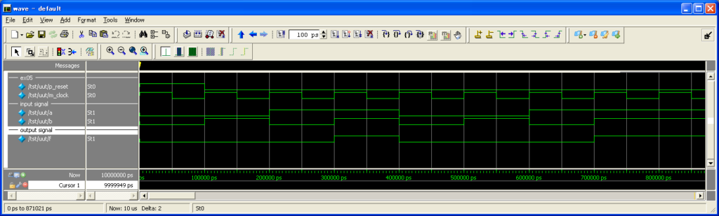
It is understood that the result of the logical AND is output to “f” corresponding to the input of “a” and “b”.
3-2. Explanation of parallel action
The hardware description language executes a described action simultaneously.
It is called a parallel action to execute it simultaneously like this.
So, let’s see Example 6 as an example of the parallel action.
declare ex06 {
   //Declaration of input/output structure element
   input a, b ;
   output f, g ;
}
module ex06 {
   //Common action description
   f = a ^ b ;
   g = a | b ;

}
|
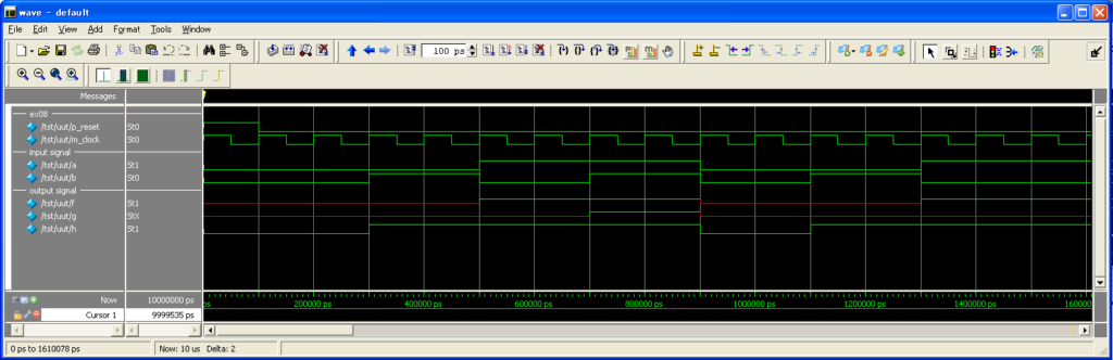
It is understood that the exclusive OR is transferred to “f”,
and the logical OR is done to “g” corresponding to the input of “a” and “b”.
3-3.When multi-bit signal is used
When designing with HDL, multi-bit signal is often used not only the single-bit signal.
In this manual, the multi-bit signal line is called a bunched-line signal,
and the one-bit signal is done a single-line signal.
Then, an example of the bunched-line signal is made.
Let’s see Example 7.
declare ex07 {
   //Declaration of multi-bit input/output structure element
   input a[8], b[8] ;
   output f[8] ;
}
module ex07 {
   //Common action description
   f = a & b ; //Expression 1
}
|
Example 7 shows a module that involves only “declaration of data terminal” and “common action description”.
The module in Example 7 has 8-bit data input terminal “a” and “b”, and 8-bit data output terminal “f”.
And, the logical AND of “a” and “b” is output to “f” in the expression 1.
So, let’s see the following simulation result.
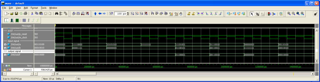
The operator “&” in Example 7 is the one that implements a bit-by-bit logical operation.
Each bit-by-bit logical AND of the data input terminal “a” and “b” outputs it to the data output terminal “f”.
3-4.Explanation of block
A syntax that describes an action is called “Atomic action”.
And, the one that describes the rule to activate the atomic action is called “Block”.
The block indicates the area enclosed with {} in an action description,
and the type includes “if”, “any”, “alt”, “parallel operation”, and “seq”, etc.
NSL designs a module by combining the blocks.
Table 9 shows the syntax of action and the type of block.
| Type | Explanation |
|---|---|
| Atomic action | Transfer of value, Write to register/memory,
Activation of procedure, Activation of control terminal, Creation of condition variable, etc. |
| if syntax | Conditional action. |
| “any” block | Conditional action.
All the actions that meet the condition are activated in parallel. If “else” action has been specified, “else” action is activated when it does not meet any condition. |
| “alt” block | Conditional action with priority level.
It activates the first action that meets the condition. If “else” action has been specified, “else” action is activated when it does not meet any condition. |
| Parallel operation block | Parallel activation of multiple atomic actions |
| “seq” block | Sequential action. (Only in control terminal) |
| “for” block | Conditional loop action.(Only in “seq” block) |
| while block | Conditional loop action.(Only in “seq” block) |
In addition, since the syntax of “seq” block, “for” block,
and “while” can be used only in the control terminal,
it is explained in the next “Chapter 4 Control terminal”.
3-5. Explanation of “if” syntax
“if” syntax is a conditional syntax that decides an action by the conditional expression.
When the conditional expression is true, it executes the action description described just after “if”.
And, when the conditional expression is false, the action just after “if” is not executed.
“if” syntax is described with the following expression.
if (Conditional_expression) Atomic_action
In addition, there is “else” syntax that executes an action
when the conditional expression of “if” syntax is false.
The “else” syntax is described as follow.
if (Conditional_expression) Atomic_action_1
else Atomic_action_2
Based on the above description, let’s see Example 8 “Description example of “if” syntax”.
declare ex08 {
   input a, b ;
   output f, g, h ;
}
module ex08 {

	//Expression 1
	if(a == 0b1) f = 0b1 ;

	//Expression 2
	if(a & b) g = 0b1 ;

	//Expression 3
	if(a | b) h = 0b1 ;
	else h = 0b0 ;
}
|
In a conditional expression, “true” indicates “Other than 0″, and “false” does “0″.
The condition is not changed even when it is multi-bit.
In Example 8, the operation may change depending on the conditional expression of “if” syntax.
The expression 1 in Example 8 is an action
that operates “If the value of “a” is 1, 1 is assigned to “f”.”.
In the same way, the expression 2 is an action
that operates “If the logical AND of “a” and “b” is true, 1 is assigned to “g”.”.
Furthermore, the expression 3 is an action
that operates “If the logical OR of “a” and “b” is true,
1 is assigned to “h”, and if the logical OR of “a” and “b” is false, 0 is assigned to “h”.”.
So, let’s see the simulation result of Example 8.
“x” of the simulation result means an indeterminate value.
3-6. Explanation of “any” block
There is “any” block as another syntax that describes a conditional action.
The “any” block can write multiple conditional expressions in a block.
As for the “any” block, the action descriptions
that satisfy the condition in the block are all activated.
The description method of “any” block is as follows.
any {
Conditional_expression_1 : Atomic_action_1
Conditional_expression_2 : Atomic_action_2
…
else : Atomic_action_x
}
The conditional expression of “any” can be both single and multiple.
And, “any” block includes the “else” syntax that is executed when all the conditions are false.
The “else” syntax may be omitted.
Then, the usage example of “any” block is explained.
Let’s see the following Example 9.
declare ex09 {
   input a, b ;
   input c, d ;
   output f, g, h ;
}
module ex09 {

   any {
      //Expression 1
      c : f = a & b ;

      //Expression 2
      d : g = a ^ b ;

      //Expression 3
      else : h = a | b ;
   }
}
|
Example 9 is a module that has Declaration of data terminal,
and Action description of “any” block .
The expression 1 in Example 9 is an action that operates
“When “c” is true, logical AND of “a” and “b” is output to “f”.”
And, the expression 2 is an action that operates
“When “d” is true, exclusive OR of “a” and “b” is output to “g”.”
Furthermore, the expression 3 is an action that operates
“When both “c” and “d” are false, logical OR of “a” and “b” is output to “f”.”
So, let’s confirm the action.
The result of the logical simulation is shown as follows.
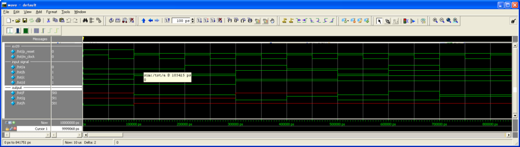
The data output terminal “f”, “g” and “h” have changed depending on the value of “c” and “d” that are described in the conditional expression.
It becomes an indeterminate value when no value is assigned to the data output terminal.
In addition, an error may occur depending on the processing system when it is transferred to the same terminal at the same time like the below.
any {
c : f = a ;
d : f = b ;
}
3-7.Explanation of “alt” block
The “alt” block is a syntax that describes a conditional action.
The big difference from “any” block is the point
that the priority level exists in a conditional action.
As for the “alt” block, the priority level of an action goes up
in order of being described from the top.
Therefore, when two conditional expressions or more are “true”,
only the action description that was described earlier is executed.
The description method of “alt” block is as follows.
alt {
Conditional_expression_1 : Atomic_action_1
Conditional_expression_2 : Atomic_action_2
…
else : Atomic_action_x
}
The conditional expression can be both single and multiple as in the same case as “any”.
And, it can use the “else” syntax that is executed when all the conditions are false.
The “else” syntax may be omitted.
So, let’s see Example 10 as a description example of “alt” block.
declare ex10 {
   input a, b ;
   input c, d ;
   output f ;
}
module ex10 {

   alt {
      //Expression 1
      c : f = a & b ;

      //Expression 2
      d : f = a ^ b ;

      //Expression 3
      else : f = a | b ;
   }
}
|
Example 10 is a module that has
“Declaration of data terminal”,and “Action description of “alt” block”.
The expression 1 in Example 10 is an action that operates
“When “c” is true, logical AND of “a” and “b” is output to “f”.”
And, the expression 2 is an action that operates
“When “d” is true, exclusive OR of “a” and “b” is output to “f”.”
Furthermore, the expression 3 is an action that operates
“When both “c” and “d” are false, logical OR of “a” and “b” is output to “f”.”
The simulation result is as follows.
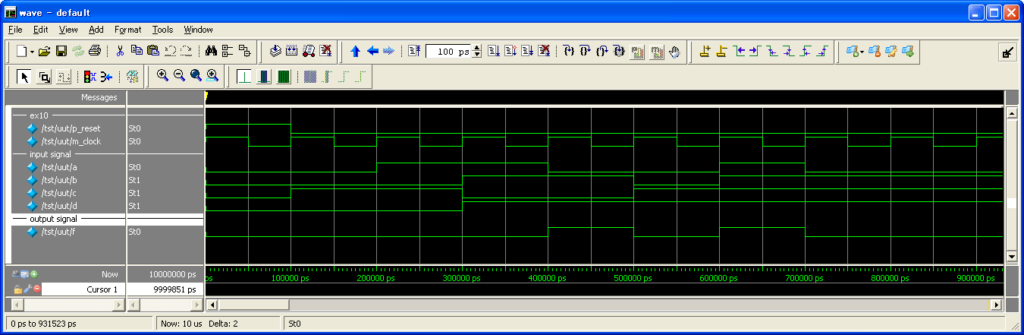
Seeing the simulation result, the action has changed in the “alt” block depending
on the value of the conditional expression “c” and “d”.
And, it is shown that there is a priority level for the conditional expression.
3-8.Explanation of parallel operation block
There is the parallel operation block as a syntax that describes a parallel action.
The parallel operation block can describe a parallel operation
by being used for the part where only the atomic action essentially can be written.
(Conditional action and sequential action, etc.)
The description method of the parallel operation block is shown as follows.
{
Atomic_action_1
Atomic_action_2
…
}
As mentioned above, the action description that operates in parallel is arranged in {}.
Let’s see the following Example 11.
declare ex11 {
   input a, b ;
   output f[2] ;
}
module ex11 {

   reg r1[2] = 0b00;

   alt {
      a : { //Start of parallel operation block
         r1 := 0b10 ;
         f = r1 ;
      } //End of parallel operation block

      b : {
         r1 := 0b01 ;
         f = r1 ;
      }

      else : {
         r1 := 0b11 ;
         f = 0b00 ;
      }
   }
}
|
Example 11 is a module that has “Declaration of data terminal”,
and “Action description of “any” block” that uses a parallel operation block.
The expression 1 in Example 11 is an action that operates “When “a” is true,
1 is output to “f” and “g” respectively.”.
And, the expression 2 is an action that operates “When “b” is true, 1 is output to “f”,
and 0 is done to “g” respectively.”.
The expression 3 is an action that operates
“When “c” is true, 0 is output to “f”, and 1 is done to “g” respectively.”.
Furthermore, the expression 4 is an action that operates
“When “a”, “b”, and “c” are all false, 0 is output to “f” and “g” respectively.”.
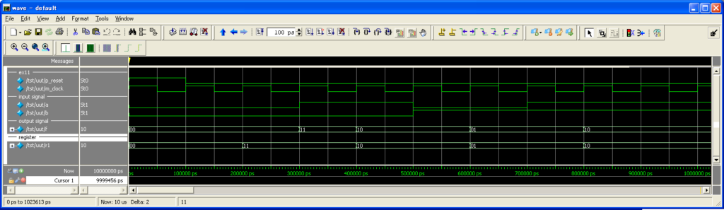
As Example 11, it is possible to implement a parallel operation after the conditional branch
when the parallel operation block is used with a conditional action.
The simulation result of the example is shown as follows.
3-9.Processing method of bunched-line signal
In this Chapter 3 Section 9,
it explains the processing method of the bunched-line signal
that is glanced in Chapter 3 Section 3.
Bit coupling
The bit-coupling operator is an operator that couples a signal and a numerical value,
and makes a signal in two or more bits.
The bit-coupling operator is used as follows.
{ sigA, sigB, … }Let’s see Example 12 as an example of the bit coupling.
declare ex12 {
   input a[4], b[4] ;
   output f[8], g[8] ;
}
module ex12 {
   f = { 0b0000, a } ; //Expression 1
   g = { a, b } ;      //Expression 2
}
|
In Example 12, the two bit-coupling operations are implemented.
The expression 1 operates “The value of “0000″
in 4-bit binary is coupled with “a”, and it is output to “f”.”.
And, the expression 2 is an action
that operates “”a” is coupled with “b”, and it is output to “g”.”.
Let’s see the simulation result of the following Example 12.

Clipping out of bit
The bit clip-out operator is an operator
that takes out only the specified bit from the multi-bit signal.
It can easily implement various processes of the signal
by combining the bit clipping out and the bit coupling.
Let’s see Example 13 as an example of the bit clipping out and the bit coupling.
declare ex13 {
   input a[8], b[8] ;
   output f[4], g[8] ;
}
module ex13 {

	f = a[3:0] ;   //Expression 1
	g = { a[6:5], b[6:1] } ;  //Expression 2
}
|
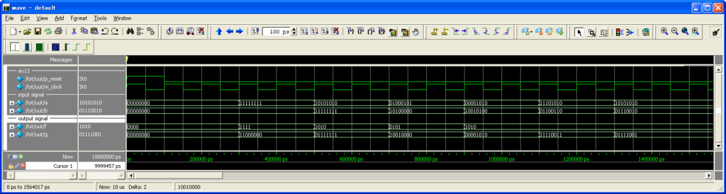
The expression in Example 13 operates “3-0 bit(s) of “a” is output to “f”.”.
And, the expression 2 is an action that operates
“6-5 bit(s) of “a” is coupled with 6-1 bit(s) of “b”, and it is output to “g”.”.
The simulation result of Example 13 is as follows.
Sign extension
The sign extension is an operator that bit-extends a numerical value in two’s complement while the sign is left as it is.
The sign extension is used as described as follows.
<Bit number to be extended>#<Signal and value to be extended>Let’s see Example 14 as an example of the sign extension.
declare ex14 {
   input a[4] ;
   output f[8] ;
}
module ex14 {
   f = 8#a ; //Expression 1
}
|
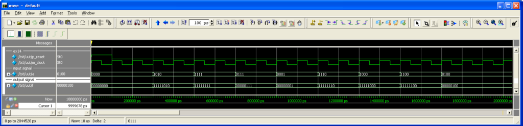
The expression in Example 14 is an action that operates
“4-bit signal “a” is sign-extended to 8 bits, and it is output to “f”.”.
Please use a bit coupling not a sign extension
when it is wanted to simply add the fixed bit(s) to the left.
The following is the simulation result of Example 14.
3-10.Operator and others
In this section, it explains how to use the operator of NSL.
Reduction operation
The reduction operation is an operation
that implements the logical operation of a multi-digit signal one by one.
For example, if the reduction operator “&” is used
when the value of the 4-bit signal “a” is 1010, it becomes as follows, and the result is 0.
1 & 0 & 1 & 0
In addition, the description during a behavioral description is implemented together with the signal as follows.
&sigALet’s see the following Example 15 as an example of the reduction operator.
declare ex15 {
   input a[4] ;
   output f, g, h;
}
module ex15 {

   f = &a ; //Expression 1
   g = |a ; //Expression 2
   h = ^a ; //Expression 3
}
|
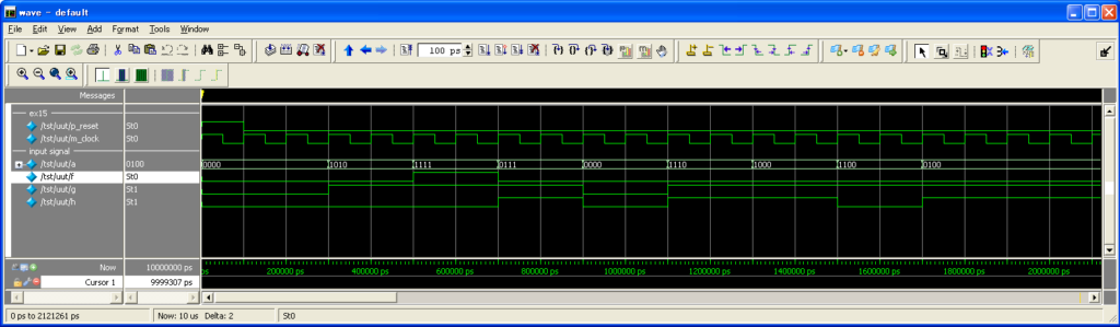
The expression 1 is the same meaning as “&a”, that is the following description.
f = a[3] & a[2] & a[1] & a[0]And, since the expression 2 is “|a”, it is the same meaning as the following description.
g = a[3] | a[2] | a[1] | a[0]Furthermore, since the expression 3 is “^a”, it is the same meaning as the following description.
h = a[3] ^ a[2] ^ a[1] ^ a[0]The simulation result of Example 15 is as follows.
Arithmetic operation
The arithmetic operation permits addition, subtraction, and multiplication.
The addition, the subtraction, and the multiplication provide an operational circuit that ends in one clock.
Let’s see the following Example 16 as a usage example of the arithmetic operation.
declare ex16 {
   input a[4], b[4] ;
   output f[4], g[4], h[8] ;
}
module ex16 {

   f = a + b ; //Expression 1
   g = a - b ; //Expression 2
   h = a * b ; //Expression 3
}
|
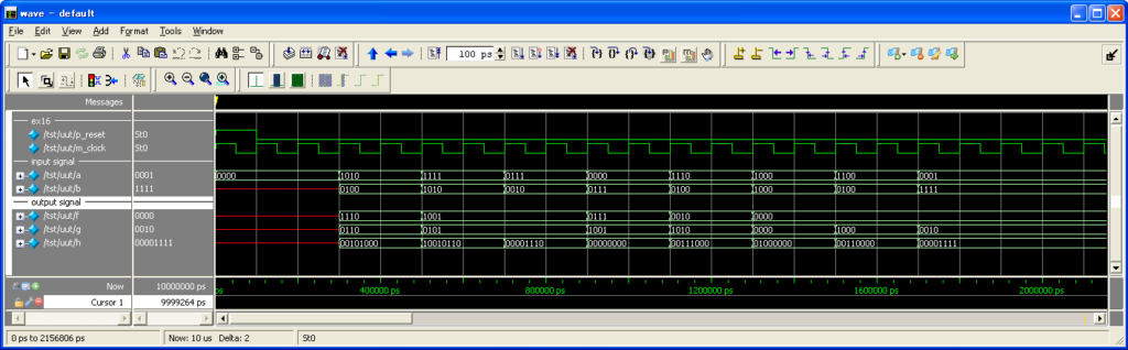
Example 16 indicates the arithmetic operation.
The arithmetic operation supports the addition, the reduction, and the multiplication.
The expression 1 is an action that transfers the sum of “a” and “b” to “f”.
The expression 2 is an action that transfers the difference between “a” and “b” to “f”.
The expression 3 is an action that transfers the product of “a” and “b” to “f”.
Let’s see the simulation result of Example 16.
Shift operation
The shift operation is an operation that slides the digit of the bit to right and left while leaving the bit length as it is.
In case of the left shift, the value that is added from the right always becomes “0″.
Also, in case of the right shift, the value that is added from the left always becomes “0″.
In addition, in case of both the shifts, the value shifted beyond the primary bit length is rounded down.
For example, it becomes 1100 when 0011 was shifted by 2 bits to the left.
Let’s see the following Example as an example of the shift operation.
declare ex17 {
   input a[8] ;
   output f[8], g[8] ;
}
module ex17 {

   f = a<<4 ; //Expression 1
   g = a>>5 ; //Expression 2
}
|
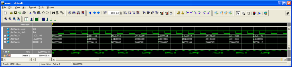
Example 17 is an example of the shift operation.
The expression 1 is an atomic action that means
that the signal a is shifted by 4 bits to the left, and output to “f”.
The expression 2 is an atomic action that means
that the signal b is shifted by 5 bits to the right, and output to “g”.
Let’s see the simulation result of Example 17.
Logical operation
The logical operation, differing from the bit operation is an operation
that operates the signal itself to be operated with “true” and “false”.
Even a multi-bit signal is “true” if it is other than 0.
Also, even a multi-bit signal is “false” if it is 0.
Let’s see the following Example 18 as an example of the logical oration.
declare ex18 {
   input a[4], b[4] ;
   output f, g, h ;
}
module ex18 {

   if(!a) f = 0b1 ; //Expression 1
   else f = 0b0 ;

   if(a&&b) g = 0b1 ; //Expression 2
   else g = 0b0 ;

   if(a||b) h = 0b1 ; //Expression 3
   else h = 0b0 ;
}
|
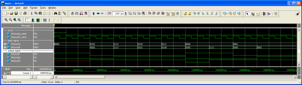
A logical operation is implemented in Example 18.
The expression 1 conditionally judges logical NOT of “a”, and indicates an action
that 1 is output to “f” for “true”, and 0 is done to “f” for “false”.
The expression 2 conditionally judges logical AND of “a” and “b” by the “if” syntax,
and indicates an action that 1 is output to “g” for “true”, and 0 is done to “g” for “false”.
The expression 3 conditionally judges logical OR of “a” and “b” by the “if” syntax,
and indicates an action that 1 is output to “h” for “true”, and 0 is done to “h” for “false”.
So, let’s see the simulation result of Example 18.
Repeat operation
The repeat operation is an operator that prepares multiple bits of the repeat with the same value.
For example, it describes as follows when 1 is prepared as many as 10 bits.
10{0b1}Actually, it becomes the same description below.
0b1111111111Let’s see the following Example 19 as an example of the repeat operation.
declare ex19 {
	output f[8] ;
}
module ex19 {
	reg r1[8] ;

	r1 := 8{0b1} ; //Expression 1
	f = r1 ;
}
|
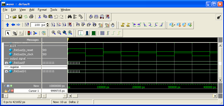
The repeat operation in Example 19:
The expression 1 is an atomic action that has the same meaning as the following.
r1 = { 0b1, 0b1, 0b1, 0b1, 0b1, 0b1, 0b1, 0b1 }Let’s see the following simulation result.
Conditional operation
The conditional operation is an operator of conditional branch
that is used when a signal and a value are transferred.
The signal/value to be transferred to the right-hand side can be sorted
by case by using a conditional operation when transferring.
The description method of the conditional operation is as follows using “if” and “else”.
sigA = if(Conditional syntax) Signal/value else Signal/valueNext, more concrete description example of the conditional operation is shown.
sigA = if(sigB) sigC else 0b1 ; //Expression 1The expression 1 is an action that means that sigC is transferred to sigA when sigB is true,
and 0b1 is transferred to sigA when sigB is false.
Let’s see the following Example 20 as an example of the conditional operation.
declare ex20 {
	input a[4] ;
	input b[2] ;
	output f[4], g[4] ;
}
module ex20 {

	f = if(b == 0b10) a else 0b1010 ;          //Expression 1
	g = a + if(b == 0b01) 0b0101 else 0b0011 ; //Expression 2
}
|
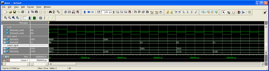
The expression 1 in Example 20 is an action
that “a” is transferred to “f” when “b==0b10″ is true, and 0b1010 is transferred to “f” when it is false.
And, the expression 2 is an action that “a+0b0101″ is transferred to “g” when “b==0b01″ is true,
and “a+0b0011″ 0b1010 is transferred when it is false.
Let’s see the simulation result of the following Example 20.
increment and decrement of register
Increment indicates that 1 is added to a variable value,
and it is rewritten to the value, and decrement does that 1 is subtracted from a variable value,
and it is rewritten to the value.
In NSL, there is the atomic action that can increment and decrement to the register.
Notes: ++ and — are not an operator.
A varied numerical value is reflected in the register at the next clock.
Using “++” when add one to the register, and “–” when subtract one from it,
it is described as follows.
Register_name++
Register_name–
Description example 10 shows an example
that uses the basic atomic action that has come out so far.
declare ex21{
   output f[4], g[4] ;
}
module ex21 {
   reg r1[4]=0, r2[4]=0 ;

   r1++ ; //Expression 1
   r2-- ; //Expression 2

   f = r1 ;
   g = r2 ;
}
|
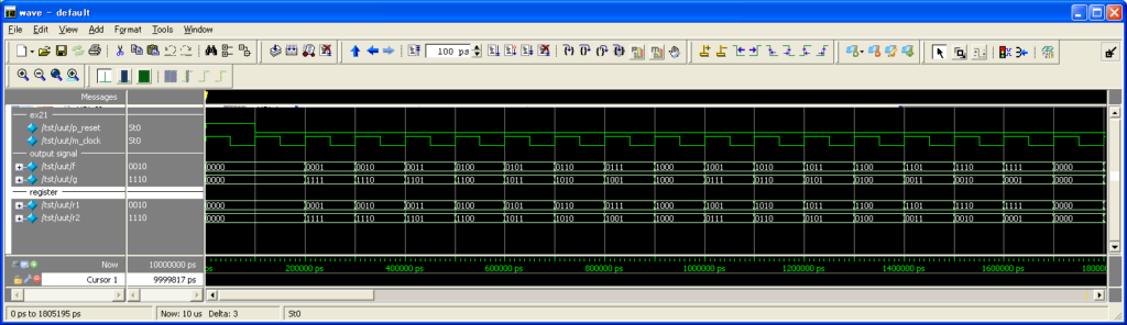
Description example 21 shows an example of increment and decrement .
The expression 1 is an atomic action that has the same meaning as the following.
r1 := r1 + 0×1The expression 1 is an atomic action that has the same meaning as the following.
r2 := r2 + 0×1Let’s see the simulation result of the following Example 21.